Hexapod
·I worked on this project during my first two years of university in the Integra student research group. My contribution was software (both for controlling the robot and stereo vision).
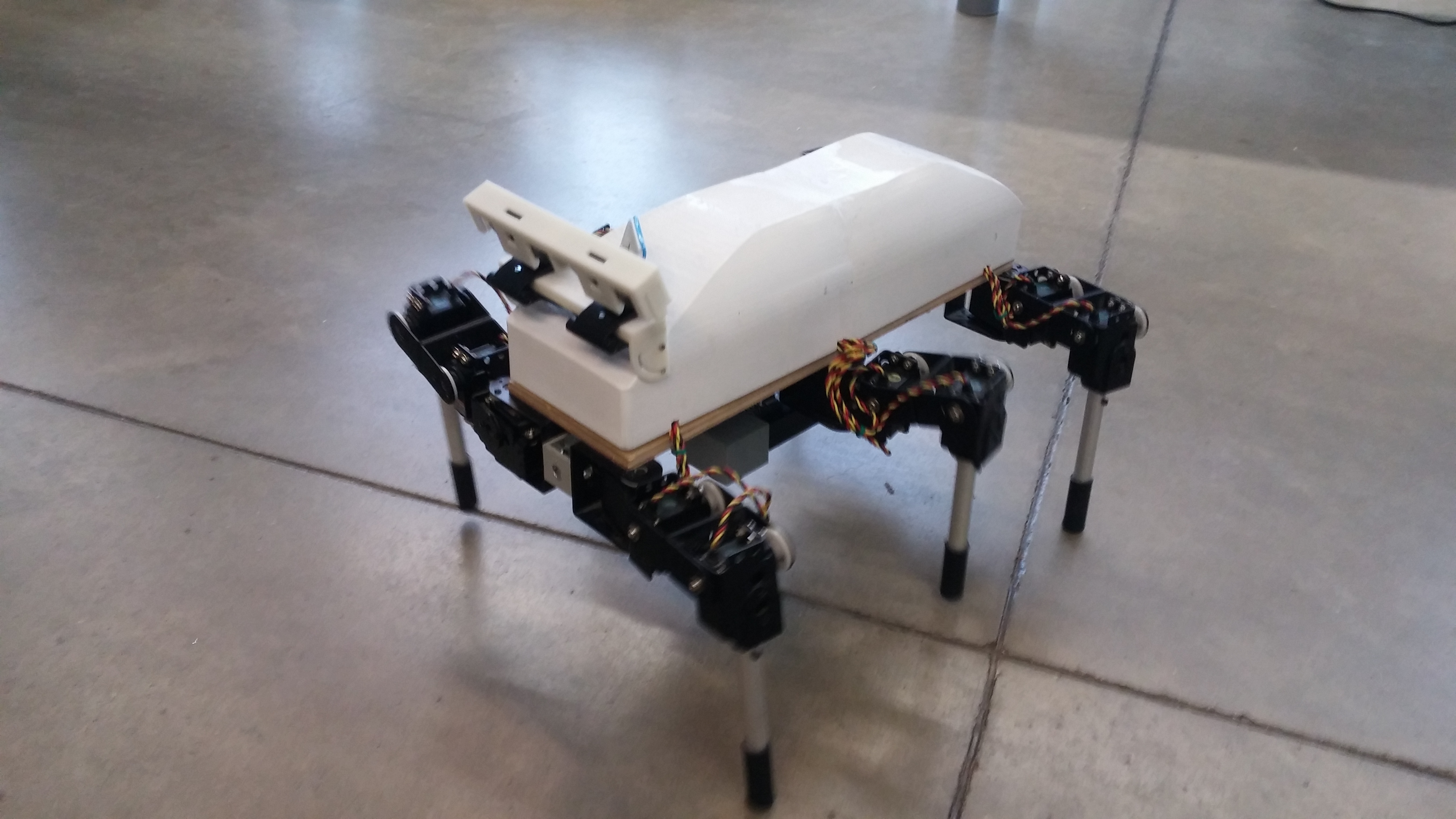
In the robot construction 18 Hitec servos (3 for each leg) were used. Raspberry Pi 2 was the main brain of the robot, it controlled servos through the Pololu driver (using UART communication). 4000mAh LiPol battery allowed for around 1h work time, voltage converters were necessary (3 for servos and 1 for Raspberry). MCP3008 ADC was used to measure battery voltage, it sent current value using SPI to the Raspberry, which was later sent and displayed in the client application.
The robot can be controlled using a gamepad or keyboard connected to the laptop, which sends commands to the Raspberry using TCP and WiFi. Using a mathematical model of the robot, the control application calculates the position of the tip of the leg to achieve the desired movement. Then it is converted to joint angles using inverse kinematics, which are used to calculate PWM signals sent to servos.
Robot control
PC Client Application Github repository Raspberry Application Github repository
Application run on laptop includes robot model and sents user commands over to Raspberry Pi mounted on the robot. They are then converted into PWM signals used for servo control. The current battery voltage is sent back from Raspberry to the client application.
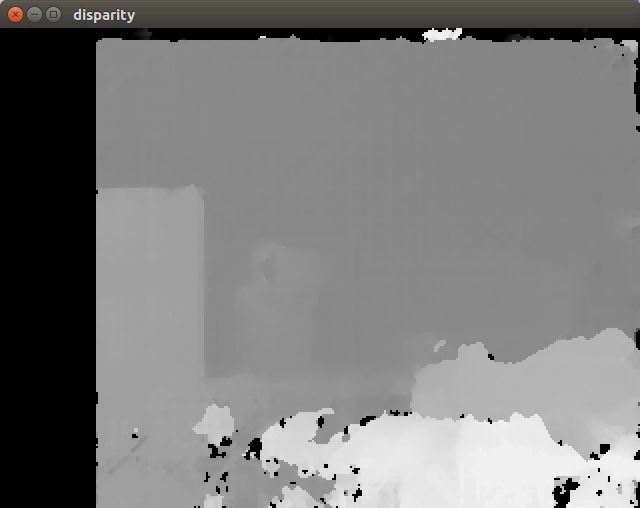
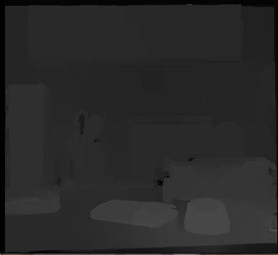
A separate application is used for stereo vision. Using GStreamer image streams from both cameras are sent from Raspberry to the main application run on a laptop. Then they are processed and disparity image is calculated, which is later used to get information about the distance to obstacles nearby.
The client application can work in 2 modes:
Simulation mode
In simulation mode camera can be controlled using keys W/S/A/D/Q/E and alfa, beta and gamma bars (for changing camera angles). The robot can be controlled using w/s/a/d/q/e and numerical keys to choose a walking mode.
Hexapod connection mode
When the Raspberry Pi address is passed to the client application, it additionally connects to it and sends commands to the robot.
A more detailed description of implementation:
GUI
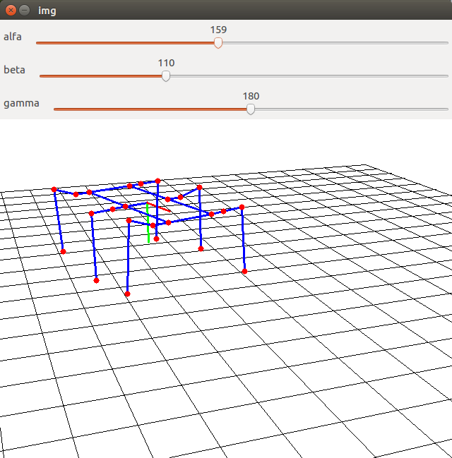
The GUI of the application was realized using OpenCV, the camera was simulated using 3D projection 1. The whole simulated world was projected onto a camera plane, which can be moved around the environment.
Robot
This main module is responsible for all calculations necessary for controlling the robot. It includes inverse kinematics implementation (using 2).
Walking
It generates trajectory points for the tip of the leg to get to the desired position (various approaches were tested, and the best results were achieved with parabolic trajectory). Then using inverse kinematics they are translated into joint commands.
Other modules
It was also necessary to implement conversion between desired joint angle and the PWM signal (it required calibrating servos).
TCP
The TCP module is responsible for communication between Raspberry and the client application. It was based on 3. Battery voltage is read on the Raspberry (in a separate thread) and sent on port 8081, which is later read by the client application and shown on the screen. On port 8080 client application sends control commands to the Raspberry.
Stereo vision
Stereo Vision Github repository
Calibration images
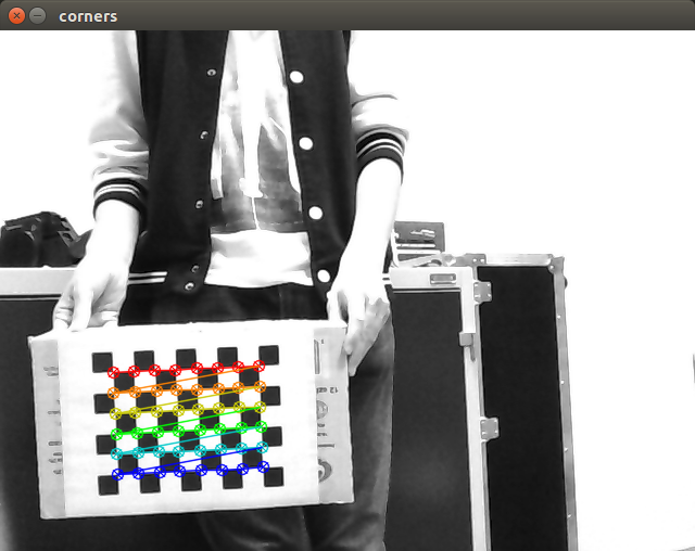
To calibrate pair of stereo vision cameras it is necessary to take several pictures of some pattern, in this case it was a chessboard. For this purpose I saved around 50 images with chessboard pattern in different positions and orientations.
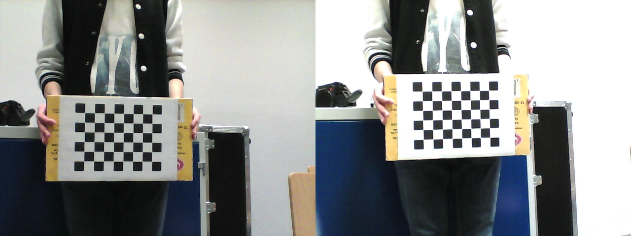
There was one problem with the cameras’ mounting - they weren’t properly aligned. This shift was fixed during calibration, but as a result, the stereo vision field of view is slightly decreased.
Calibration
Calibration was based on the example from the book “Learning OpenCV”. As input it required the number of rows and columns of the chessboard and the length of one square side (it was important to print the chessboard in original proportions so that squares won’t become rectangles, which will break the calibration process).
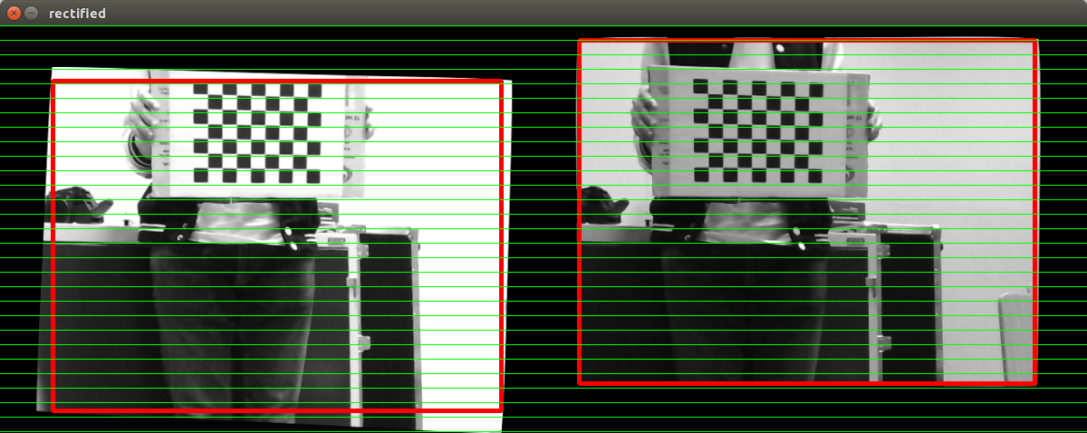
The result of the calibration was intrinsic and extrinsic camera parameters, errors of this process were: Mean square error (RMS) = 0.0503053 Epipolar mean error = 0.517146 These error values are quite low, which means that calibration was successful.
Algorithm and parameters
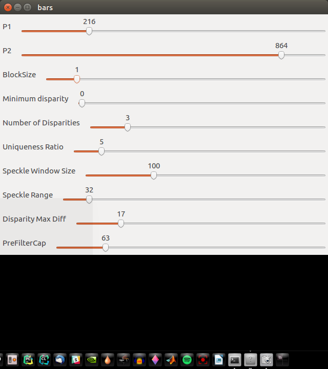
I tested SGBM and BM algorithms from the OpenCV library, better results were achieved for SGBM. CPU usage was higher for this algorithm, but still it was possible to get real-time results for images with 320x240 resolution. Then I tuned the parameters of the SGBM algorithm, using the application that allowed dynamic reconfiguration of parameters using sliders.
Postfiltration parameters
To get a smoother result I additionally used postfiltration from contrib OpenCV modules.

Application
The final application combined all the elements described above - video stream from cameras connected to Raspberry was sent to the laptop, then images were rectified, pixels matched using SGBM, disparity image calculated and then filtered. Finally disparity was displayed on the screen, as the next step it should be used to calculate the point cloud, which then could be used for obstacle detection.
Getting satisfactory video transmission wasn’t that easy. In the first approach MJPGstreamer was used, but the results weren’t too good - all frames were buffered and as it wasn’t possible to send them in real-time, the delay between registering the image and analyzing it using stereo vision was increasing. Additionally images from two cameras weren’t synchronized. So instead I used GStreamer, which was more tricky to set up, but the results were much better. The resolution of sent images was 320x240 (for 640x480 FPS was too low).
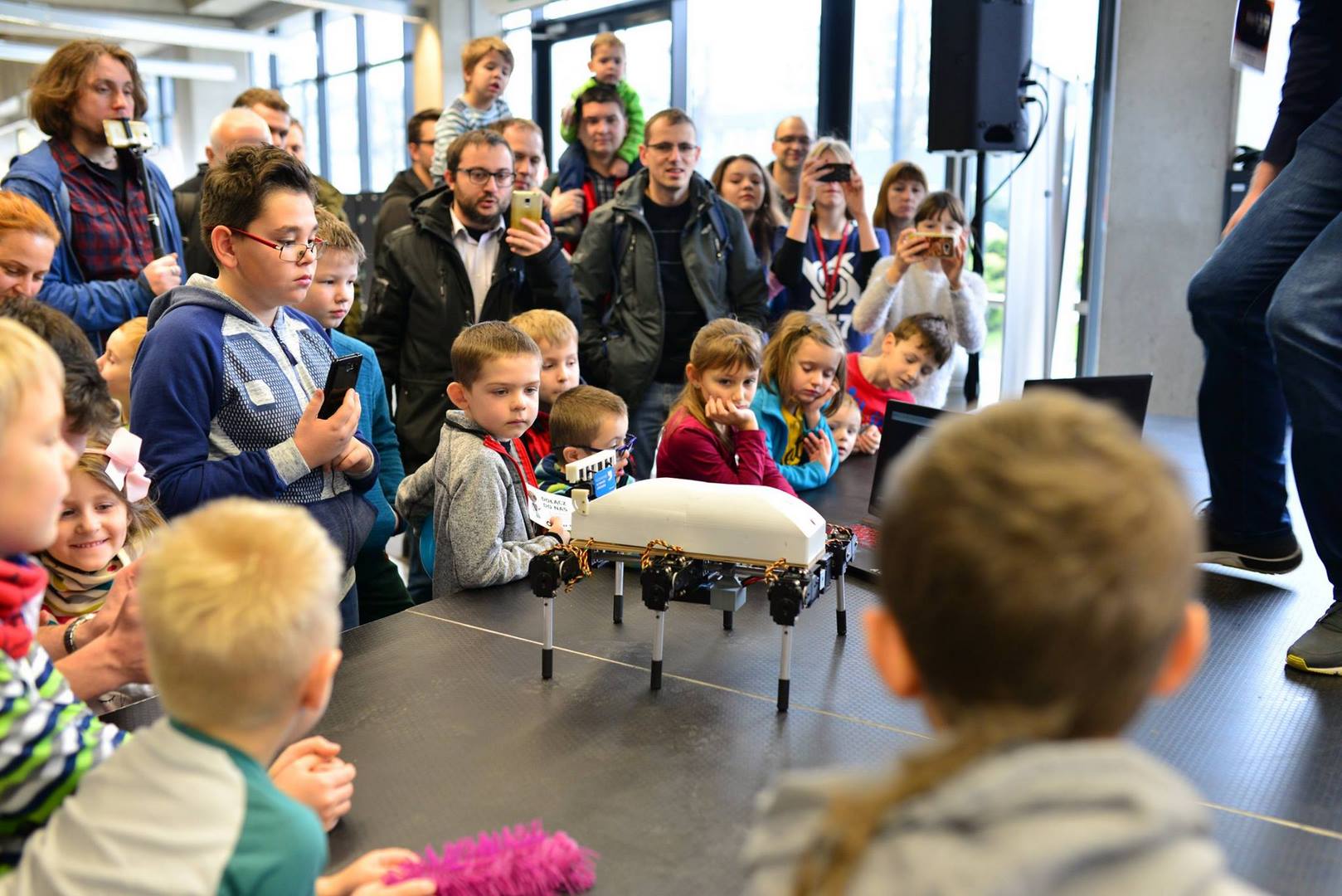
Achievements
Robotic competitions
- Robocomp 2017 in Cracow (Freestyle category)
- Robotic Arena 2017 in Wrocław (Freestyle and Robosprint). 1st place in Robosprint.
- Robomaticon 2018 in Warsaw (Freestyle)
- Robotic Tournament 2018 in Rybnik (Freestyle)
- Robotic Arena 2019 in Wrocław. 2nd place in Robosprint.
- Robocomp 2019 in Cracow. 3rd place in Robosprint
- Robotic Arena 2020 in Wrocław. 3rd place in Robosprint.
Events
- Targi pracy Kariera IT
- TEDxAGHUniversity